NASC Science and Technology
Science & Technology
The NASC Science and Technology Group is responsible for successful product advancement through each stage of development. Our engineering team is uniquely engaged in each process required to bring many NASC products from initial concept to ultimate release. NASC Science and Technology utilizes typical theoretical engineering analysis to support the development of Unmanned Aerial Vehicles, on-board sensors, and command and control equipment.
Additionally software analysis tools are used to conduct modeling and simulation to provide very comprehensive design and development of these systems. Our function in the organization includes: technical analysis, design, producing functional prototypes, testing, and production support, described below.
Technical Analysis
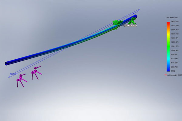
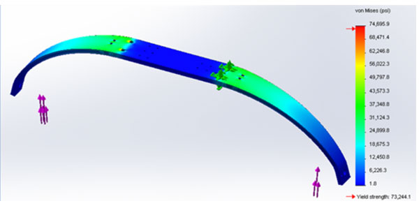
The development of systems require analyzing the strength of components and assemblies to determine if they can withstand forces imparted during the functioning or service conditions during operation of the system. The first step in the analysis is to determine the loads imparted to the device. These loads can be either static or dynamic. Next, material type is selected. Then the strength of the material is chosen which will exceed the stress imparted by the loads applied. The structural analysis software program provides a meshing function which is the basis for the analysis. The applied loads are the input forces used in the finite element analysis. The program calculates the stress and deflections in the component, or the assembly. The results of the analysis determines if the selected material and geometric design has strength higher than the allowable stress of the material, and if predicted deflections are not detrimental to the system function. New material or geometry may need to be changed and analyzed if predicted stress and deflection is not acceptable.
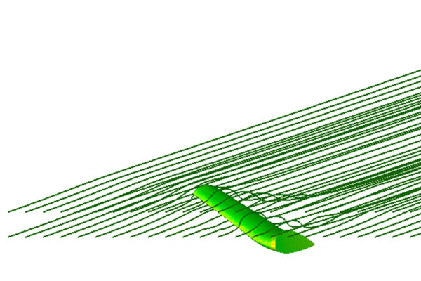
Aerodynamic performance of our Unmanned Air Vehicle systems is an important aspect of this product. This performance is a function of the lift and drag produced by the vehicle, or the drag developed during flight from external payloads carried on the aircraft. Simulation tools are used to model the aircraft aerodynamic performance. Three dimensional mechanic models of the object being studied is imported and the program conducts the computation. Airspeed, altitude, and angle of attack are input variables which are varied depending on the operational parameters. Lift and drag values are provided by the analysis. Flow field characteristic are shown as streamlines representing the behavior of the flow around the body being analyzed.
Aircraft stability describes the response of the aircraft to external perturbation. The location of the aircraft center of gravity relative to the center of pressure acting on the aircraft will determine whether the aircraft configuration is stable or not. A stable aircraft will have a lot of inherent aerodynamic damping so that external disturbances will not affect the flight behavior, positive damping. Our modelling program includes a representation of the wing, tail, and body of the aircraft. The specific dimensional configuration, in addition to airfoil configurations are modeled. The airspeed and altitude of the flight being simulated is input to the analysis tool. The program provides an assessment of the vehicle and will determine if the configuration is stable. It will also determine the flight trim angle of the aircraft.
The physics of electromagnetic optical energy and material sciences allow for the design and manufacturer of day/night imaging detectors (focal plane arrays), optical components (lenses, telescopes, etc) and associated electronics, that translate target imagery captured by an optical system, into scenes observed with a video monitor. IS&R systems utilize small optical components sensitive to the infrared and visible regions, consisting of telescopes and cameras installed into ultra-stable lightweight turret systems. Associated with these imaging systems are Solid-State Laser sources, integrated into turrets, providing artificial illumination of targets for nighttime surveillance, target spotting for the delivery of weapons and laser radars for target ranging and altimeters utilized in autonomous UAV landing systems.
The design and application process involves an interaction with Mission Specialists, UAV Pilots and Data Analysts, to establish the optimum design of a sensor suite, in an effort to meet new requirements of a CONOPS. The EO department analyzes a customer’s mission need and develops an integrated sensor solution with microwave radar, turret based optical systems or a combination of both. Our services also provide the customer with custom designed Ground Control Stations (GCS) responsible for processing imagery and data downloaded from the UAV via a RF communications link from the UAV platform.
Design
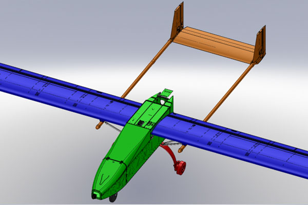
Mechanical design requires a combination of creativity and practicality. We use Solidworks 3D modeling software to assist in the mechanical design of our products. This tool provides an actual physical representation of geometry and fit of parts relative to each other in an assembly. This feature provides the ability to optimize the installation of components in complex assemblies. The program can also calculate volume, surface area, mass moment of inertia, and center of gravity.
The next step in the design process is to build a component or assembly to verify that the Solidworks design provides the intended form, fit and function. To reduce cost and time required to produce an initial prototype, we implement rapid prototyping, also called additive manufacturing. This is accomplished by using a 3D printing machine which and a Solidworks 3d STL model file. The printing machine deposits molten material on a build plate layer by layer until the build is complete. This prototype is a very useful tool to verify design goals, but it has limited functional dynamic applications since its material strength is minimal.
The Solidworks 3D software also provides the ability to easily produce drawings of components and assemblies. A drawing template is selected and the component or assembly is imported and displayed in a 3 view arrangement on the drawing sheet. Dimensions and notes are added as required. Depending on the complexity of the design, other views can be added to describe complex details. The assembly drawing includes a Bill of Materials which identifies each part in the assembly and lists the quantity of the parts used. We use PDM works, a Solidworks tool to store and keep track of parts, assemblies, and drawings.
Functional Prototype
The next step in the design process is to build a fully functional prototype. This configuration represents the design maturity which has evolved from the 3d modelling and rapid prototyping. Depending on the performance required, typically steel or aluminum materials are used. This provides a low cost approach to verifying system performance. We have complete manufacturing services which includes metal machining and sheet metal construction to produce prototypes.
Our products are aerospace oriented. This requires lightweight, high strength systems. To achieve these goals, we must at times use composite materials in our designs. This design incorporates woven fabric material impregnated with epoxy resin. Depending on the design requirements, a core may be included, and layers of cloth are applied to the top and bottom surface of the core. Fiber orientation, number of layers, and core thickness are design parameters which are selected based on performance required. We have complete manufacturing capabilities to produce composite material prototypes.
Testing
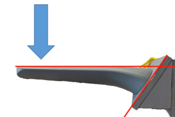
Our aerospace products must have reliable structures to provide the required performance and service life. The structural design and analysis parameters are verified by test data. Design loads are established based on required performance. Structural testing includes loading the structure being evaluated to levels which exceed the design load replicating a maximum service condition. This methodology establishes whether the design has a sufficient safety factor. The structural test includes recording imparted load, and resulting deformation. The procedure is to load the test article to a percentage of maximum, record deflection, then return load to zero. This procedure is repeated imparting progressively greater loads until test article fails. Deflection under load is measured relative to an unloaded condition to establish load/deflection characteristics of the structure. During the test cycle, as the load is increased, then removed, the structure should return to a zero deflection position. The load which cause a permanent deformation, ie, the unloaded position does not return to the zero deflection unloaded position, a yield condition has occurred. The load that caused this condition is the yield load. The testing continues with progressively higher loads until the structure fails, which establishes the ultimate strength of the structure.
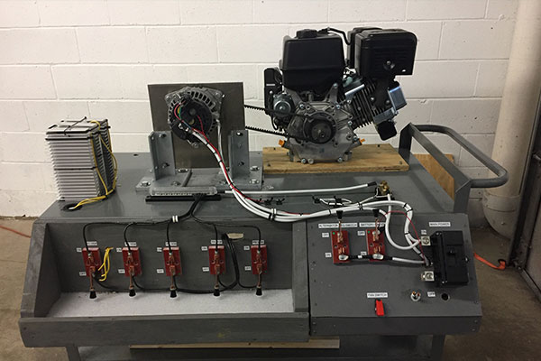
This type of testing evaluates the performance of devices in motion or conditions where cyclic or rotational loads are applied. A specific example of this type of testing is measuring alternator performance as a function of RPM. This test required developing a test stand which would drive the alternator over a range of rpm. A sufficient resistive load was applied to the alternator so that output voltage and current performance as a function of RPM could be determined. The mechanical drive system included an internal combustion engine and a pulley system which provided the required RPM. The electrical characteristics, alternator temperature and RPM where measured during the test.
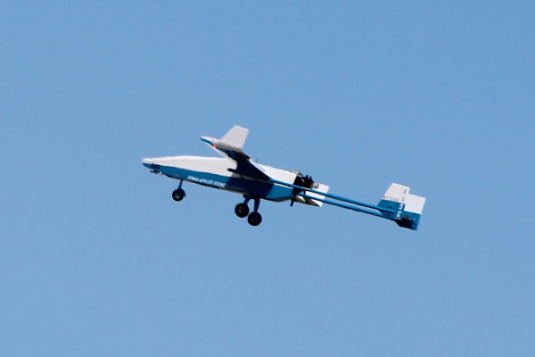
The air vehicles we develop require a mix of design, analysis, and pilot flight evaluation. The required performance, or desired performance improvement is determined based on system functional requirements. Flight testing is conducted to determine that the required performance is achieved. This testing also validates the design and analysis previously conducted. A test plan is developed as a collaboration between engineering staff and the pilots operating the aircraft. The plans are organized to provide iterative testing and includes bench mark test articles to determine if desired performance improvement is achieved. In addition to measured performance, pilot operational evaluation is an important factor in the evaluation.
Production Support
In addition to developmental tasks, production vehicle performance, reliability, and obsolescence issues are also analyzed, and solutions presented. These tasks typically build on experience we have established during the product developmental phase and provide a basis for the production issue solution.
Although the vehicle production issues are unique compared to developmental projects, the typical design/analysis/testing process is applied to both type of projects as required.

